نشریه 207-دستورالعمل استفاده از امولسيونهاي قيري در راهسازي
+ نوشته شده در شنبه ۲۸ اردیبهشت ۱۳۹۲ ساعت ۱:۴ ق.ظ توسط علی مجیدی
|
![]()
دانلود در ادامه مطلب
کتاب مکانیک برداری یا همان استاتیک جانستون یکی از کتب بسیار کاربردی میباشد. و اکثر دانشجویان نیز با آن آشنا هستند.
این کتاب به صورت یک فایل پی دی اف در 605 صفحه در اختیار شما دوستان قرار میگیرد. امیدوارم مورد
توجه شما دوستان قرار بگیرد.
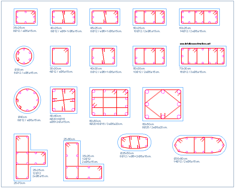
Detail Of Steel In Beams Columns
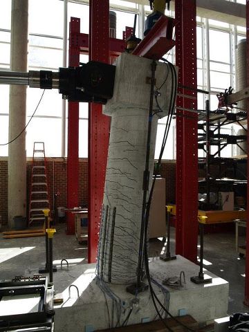
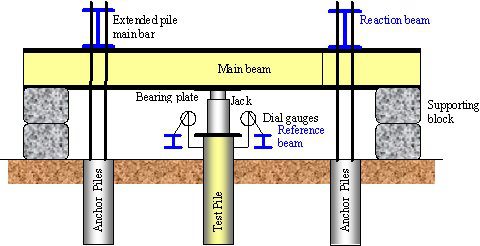
test Lateral load Bridge Columns
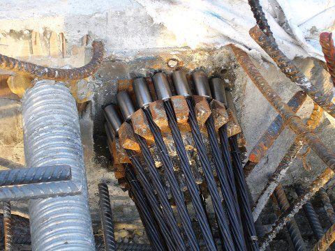
Coupler bearing plate - tension-tendons
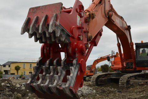
Concrete grinder
مهندسی عمران بهشهر(تیسفون)
 * مهندسی عمران و معماری بهشهر(تیسفون) *